Wooden White Gazebo 300x300x250 (L*W*H) · SS-012804
Price on request
SKU: SS-012804
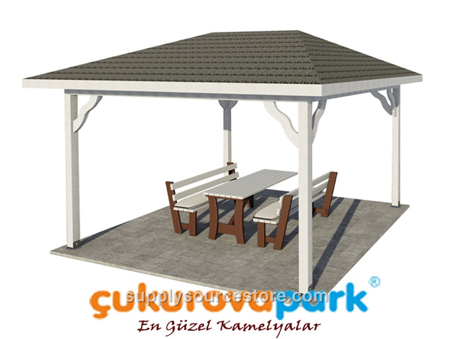
Product Features Seating Area: 300 × 300 cm (118 x 118 in) Roof Size: 370 × 370 cm (146 x 146 in) Height: 330 cm (130 in) Wood: 1st‑grade spruce/pine Wood Color: White Roof Covering: Special roofing material made of shingle over clapboard or fiberglass Shingle Color: Gray Seating Unit: None Table: None Wood Characteristics: The structure will use 1st‑grade Norway spruce (Pinus sylvestris) timber. Sections are cut with a tolerance of ±2 mm (0.1 in) and overall dimensions with a tolerance of ±20 mm (0.8 in). Each meter may contain up to four solid buds, none exceeding one‑quarter of the piece width. No rot, defects, partially fused or fallen buds are permitted. Ring cracks are prohibited; only microscopic cracks (1–2 mm (0-0.1 in)) are allowed within tolerance. Press‑impregnation may produce axial and radial cracks, but they must stay within specified limits. Resin pockets up to 10 cm (3.9 in) in length may appear once per meter; no leaking, pulling resin, inner shell, rot cavities, or insect holes are allowed. Manufacturing defects are excluded; only the defined tolerances apply. Flexural deflection will not exceed 1⁄50 of the member length, impact not more than 1⁄100 of the width, and torsion not beyond 2 mm (0.1 in) per meter. All visible surfaces will be sanded smooth and finished with a white lacquer paint. Main Supports: Four pine beams, minimum 90 × 90 mm (3.5 x 3.5 in), shaped with diamond‑point knives and decorative patterns, will form the support legs. The leg height is 240 cm (94.5 in). Roof: The gazebo roof frame consists of 50 × 100 mm (2 x 3.9 in) wooden members. Ends are milled to shape, then covered with wooden cladding or fiber material and secured with wide‑head screws. Shingles (American cedar‑shingle style) are fastened with wide‑head, specially designed screws. Additional decorative 30 × 130 mm (1.2 x 5.1 in) wooden lathe pieces are attached to the fascia with galvanized screws. The roof connection framework uses eight minimum 50 × 50 mm (2 x 2 in) members, each cut at precise angles and shaped with diamond‑point knives. All fixed connections employ stainless‑steel wood screws or polymer adhesive; galvanized wood screws are used for the main support‑to‑roof joints. Anchoring: Steel plates and dowels are installed beneath the support legs with pre‑drilled holes for 6 mm (0.2 in) screws. The anchorage system is welded to flange plates (minimum 2.5 mm (0.1 in) thickness) and secured with special screws—six per leg for the vertical connection and two per leg for the ground connection. All metal components receive a polyester‑based powder‑coat finish. Impregnation: [Details not provided]