Capital Park Gazebo – 14
Price on request
SKU: PARKS-0571
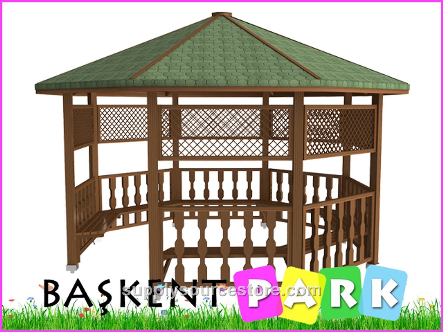
Product Technical Specifications Seating Area: 400 x 400 cm (157 x 157 in) Roof Area: 470 x 470 cm (185 x 185 in) Height: 300 cm (118 in) Wood Characteristics: The lumber used for manufacturing will be first‑class Yellow Pine (Pinus sylvestris) timber. Wood sections will be fabricated with a maximum tolerance of ±2 mm (0.1 in), and overall dimensions with a tolerance of ±20 mm (0.8 in). The wood material must meet the following criteria: knots – up to four solid knots per meter, with knot diameters not exceeding one‑quarter of the piece width; no rot, decay, partially fused, or missing knots; no ring cracks; fine hairline cracks (1–2 mm (0-0.1 in)) are permissible; pressure‑treated wood may contain head‑ and longitudinal cracks within tolerance limits; resin pockets – at most one per meter, not longer than 10 cm (3.9 in); no leaking or sucking resin, no inner shell, no rot cavities, and no insect holes. Manufacturing defects are not allowed; only deviations within the specified tolerances are acceptable. Flexibility: deflection will not exceed 1/50 of the member length. Impact marks will not exceed 1/100 of the member width. Twist: a maximum of 2 mm (0.1 in) per meter of length. Bending of the grain: tolerance between 1/50 and 1/100 of the member length. Sanding: all visible surfaces will be sanded smooth. Primary Supports: Eight 90 × 90 mm (3.5 x 3.5 in) pine beams with diamond‑shaped cutting tools and decorative motifs will be used for the support legs. The support legs will be 240 cm (94.5 in) high. Roof: The roof framing members will be 50 × 100 mm (2 x 3.9 in) timber. Two corners of each member will be shaped on a router. The top of the members will be fastened with either wooden shiplap, fiber panels, or similar material. Zinc‑coated nails with wide heads will attach the shiplap, followed by a shingle roofing system (American cedar shingles). In the fascia area, 30 × 130 mm (1.2 x 5.1 in) decorative timber pieces will be mounted with galvanized wood screws. The roof connection frame will consist of eight 50 × 50 mm (2 x 2 in) pieces, each cut at specific angles and shaped with diamond‑shaped tools; one end will attach to the primary support, the other to the fascia. All fixed connections will use stainless‑steel wood screws, while the primary‑to‑roof connections will use specially galvanized wood screws. Upper Panels: The upper guardrails are 40 cm (15.7 in) wide. Guardrail frames are 50 × 50 mm (2 x 2 in) timber, sanded on all sides and edged with a decorative diamond‑shaped blade. These frames will be mounted to the primary support with galvanized wood screws. Intermediate decorative elements are made from separate timber pieces and will be fastened with galvanized screws. Lower Panels (Guardrail): The lower guardrail height is 75 cm (29.5 in). Guardrail frames are 50 × 50 mm (2 x 2 in) timber, sanded on all sides and edged with a decorative diamond‑shaped blade, and will be attached to the primary support with galvanized wood screws. Additional decorative elements are 40 × 50 mm (1.6 x 2 in) timber pieces shaped with special diamond‑shaped blades and will be installed with galvanized screws and a clear, specialized wood adhesive. Seating Unit: The seating unit consists of eight L‑shaped wooden legs (minimum 4 × 9 cm (1.6 x 3.5 in)). One end of each leg will be attached to the primary support, the other end to the seating frame. Four decorative diamond‑shaped cuts will be made on each side of the seat frame, which will be fastened with galvanized screws. Anchorage: A flange of 18 × 13 × 3 mm (0.7 x 0.5 x 0.1 in) will be welded to the bottom of each support leg, followed by a 15 × 8 × 2 mm (0.6 x 0.3 x 0.1 in) plate with two anchor holes. Each plate will have three 6 mm (0.2 in) screw holes (15 × 8 × 2 mm (0.6 x 0.3 x 0.1 in)). Anchors will be mounted to the supports with screws and connected to the ground using steel dowels. This arrangement prevents water contact with the wood and secures the support legs to the ground. Gazebo anchors will be welded to at least two sides of a minimum 2.5 mm (0.1 in) thick flange. Six special screws will be inserted per leg for the connection to the verticals, and two dowel screws per leg for the ground connection. All metal components will be powder‑coated with a polyester‑based finish. Preservative Treatment: A preservative pressure‑treatment will be applied according to the specified standards.